
CUSTOMER ADVANTAGES:
- Basic concept made of anodized aluminum profile
- Reflector sheet made of high reflective steel
- Adaptable to all common aluminum profile construction kits
- Customized to your individual heating installation
- Variable installation due to the T-slots
- Prepared for the installation of temperature monitoring systems or individual coverings
- Integrated or customized air supply
- Designed to supply the required power for your process by short or medium wave in round or double tube design
- Combined with a comprehensive switch board cabinet, Type IC…, if required with an automatic emitter output and product temperature control, or connected to customer control cabinet
TECHNICAL DATA:
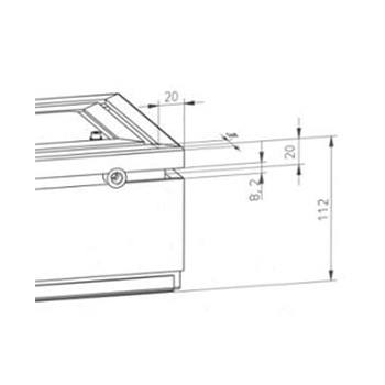
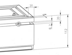
- Hight housing: approx. 112 mm
- Hight incl. axial-fan: approx. 152 mm
- Width variable: up to 2.000 mm
- Length variable: up to 4.000 mm
COOL AIR SUPPLY VIA:
- Temperature of the module is monitored by an integrated thermo switch
- VBG 23: please pay attention to regulations concerning explosion.
ELECTRICAL CONNECTION VIA:
- heavy plug-type connectors
- Internal terminals and screwed cable gland
- Designed for the connection cables Oil flex or heat resistant cable >100 °C
ADDITIONAL:
- Weight: approx. 40 kg/m²
IR MODULE 36 KW SYSTEM FOR PLASTIC CURING:
- size 1.350 x 400 x 112 mm
- structure frame made by profile L
- electr. power: 36 kW / 400 V
- 9 pc. fast medium wave single tube star 4.0 kWW
- axial fan for cooling
- heavy duty connector
- optical pyrometer
- exhaust device

IR MODUL 3.0 KW – SYSTEM FOR HEATING CD BONDING:
- Size: 440 x 290 x 112 mm
- Housing: anodized aluminum profile L
- Electrical power: 3.0 kW / 230 V
- 2 x 3 radiators short-wave 0.5 kW
- optical pyrometer
- Axial fan for cooling
- Harting connectors
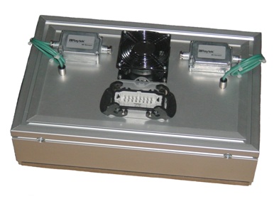
IR MODULE 3.2 KW SYSTEM FOR PLASTIC HEATING:
- size 150 x 280 x 82 mm
- housing aluminum sheet metal
- electr. power: 3.2 kW / 230 V
- 2 pc. short wave 1.6 kW
- axial fan for cooling
- heavy duty connector


CUSTOMER ADVANTAGES:
- Basic concept made of anodized aluminum profile
- Reflector sheet made of high reflective steel
- Adaptable to all common aluminum profile construction kits
- Customized to your individual heating installation
- Variable installation due to the T-slots
- Prepared for the installation of temperature monitoring systems or individual coverings
- Integrated or customized air supply
- Designed to supply the required power for your process by short or medium wave in round or double tube design
- Combined with a comprehensive switch board cabinet, Type IC…, if required with an automatic emitter output and product temperature control, or connected to customer control cabinet
TECHNICAL DATA:
- IR module 100 kW system for foil drying:
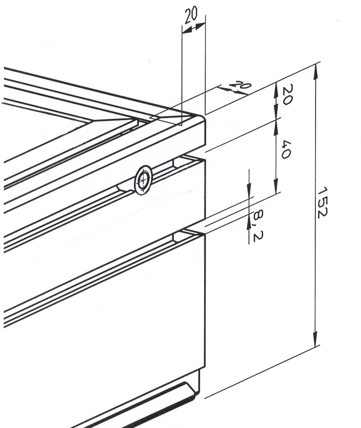
- Hight housing: approx. 152 mm
- Hight incl. axial-fan: approx. 205 mm
- Width variable: up to 2.000 mm
- Length variable: up to 4.000 mm
COOL AIR SUPPLY VIA:
- Temperature of the module is monitored by an integrated thermo switch
- VBG 23: please pay attention to regulations concerning explosion.
ELECTRICAL CONNECTION VIA:
- heavy plug-type connectors
- Internal terminals and screwed cable gland
- Designed for the connection cables Oil flex or heat resistant cable >100 °C
ADDITIONAL:
- Weight: approx. 50 kg/m²
IR MODULE 180 KW SYSTEM FOR PAPER DRYING:
- total length 3.400 x width 1.460 mm 3 single module zones: 960 x 1.200 x 152 mm
- structure frame made by profile XL
- electr. Power: 3 x 60 kW / 230 V
- 3 x 24 pc. short wave and fast medium wave single tube 2.5 kW
- radial fan for cooling
- heavy duty connector
- air knife for steam exhaust
- exhaust device
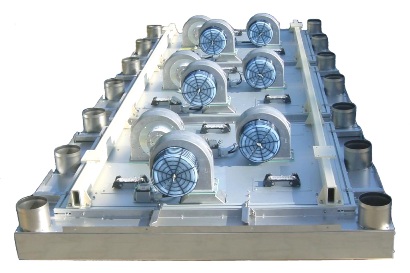
IR MODULE 100 KW SYSTEM FOR FOIL DRYING:
- size 1.960 x 700 x 152 mm
- structure frame made by profile XL
- electr. Power: 100 kW / 400 V / 230 V
- main zone 8 pc. fast medium wavedouble tube 400 V,2 x 2pc. side zone heaters 230 V
- axial fan for cooling
- heavy duty connector

IR MODULE 10 KW SYSTEM FOR HOTMELT ACTIVATION:
- size 980 x 350 x 152 mm
- structure frame made by profile XL
- electr. Power: 14 x 0.75 kW / 230 V
- fast medium wave single tube 0.75 kW
- optical pyrometer
- axial fan for coolingr
- heavy duty connector


Quartz glass plates:
Grinded plates, available in max. size 500 x 500 mm, thickness 3 - 5 mm
Pulled plates, available in sizes from ca. 100 - 180 mm width and 1.200 - 2.000 mm length, thicknes 3 - 5 mm
Quartz glass tubes in different sizes and length
Any questions? Please contact
E-Mail:
Tel: +49 (0) 6181 / 709 364
Fax. +49 (0) 6181 / 709 365

Control Desktop Heating in production variety of small power controls Types of smaller controls enabling our customers to control temperature and efficiency according to their individual needs

CONTROL IC 153
- max. Load 6 kW / 400 V
- Temperature controlled by process controller
- Main switch
- Connection to emitter by heavy duty plug
- Connection to mains by plug

CONTROL IC 151
- max. Load 3 kW / 230 V
- Density controlled by pot 0 – 100% by external signal 0 – 10 V, or external on / off
- Main switch
- Connection to emitter by heavy duty plug
- Connection to mains by plug

CONTROL IC 151
- max. Load 3 kW / 230 V
- Density controlled by pot 0 – 100%
- Main switch
- Timer
- Connection to emitter by heavy duty plug
- Connection to mains by plug

Heating in production variety of small power controls Types of control cabinets enabling our customers to control temperature and efficiency according to their individual needs
CONTROL IC 180 KW SYSTEMS FOR PAPER DRYING
- size 2.600 x 2.000 x 400mm
- max. Load 180 kW / 230 V
- 6 separate heating zones
- 3 x 24 pc. = 72 pc. short wave /fast medium wave emitter,2.5 kW each
- 3 system modes
- speed controlled
- density controlled 0 – 100 % by external signal 4 – 20 mA
- automatically start / stop mode
- exhaust air control management

CONTROL IC 100 KW SYSTEMS FOR FABRIC HEATING
- size 800 x 1.400 x 400 mm
- max. Load 100 kW / 400 V
- 2 separate heating zones
- 8 fast medium wave emitter,11.0 kW each + 2 x 2 pc. side zone emitter
- density controlled 0 – 100 % by 2 external signal 4 – 20 mA

CONTROL IC 36 KW FOIL CURING:
- Size: 600 x 780 x 350 mm
- Max. Load: 36 kW / 400 V
- 9 fast medium wave star emitter 4 kW each
- Temperature controlled by process controller or density controlled 0 – 100% by external signal 4 – 20 mA

Up to date Measurement, Control and Adjustment of ohmic load as well as Infrared emitters are the prerequisites to use Infrared systems for heating processes in an efficient and cost effective way.
| Technical Data | IC 161 | IC 163 | IC 321 | IC 323 | IC 551 | IC553 | |
| Max. output 230V load | KW | 3,5 | 10,5 | 7 | 21 | 12,6 | 38 |
| Max. phase voltage with 230V load | A | 15 | 3×15 | 30 | 3×30 | 55 | 3×55 |
| Max. output 400V load | KW | 6 | 18 | 12 | 36 | 22 | 66 |
| Max. phase voltage with 400V load | A | 15 | 3×8,5 | 30 | 3×17,5 | 55 | 3×55 |
| Nominal voltage | V | 230/400 | 230/400 | 230/400 | 230/400 | 230/400 | 230/400 |
| Kind of current | Hz | 50/60 | 50/60 | 50/60 | 50/60 | 50/60 | 50/60 |
| Mains supply Maximum safety |
CEE 5×16 |
CEE 5×16 |
CEE 5×32 |
CEE 5×32 |
Clamps | Clamps | |
| Preliminary fuse | A | 16 | 16 | 32 | 32 | 63 | 100 |
| Current type N/PE or PEN loaded phases | 1/2 | 3 | 1/2 | 3 | 1/2 | 3 | |
| Number of automatic interrupters | – | – | 6 | 6 | 8 | 24 | |
| Number of power controllers | 1 | 3 | 1 | 3 | 1 | 3 | |
| Number of possible process controllers | 1 | 3 | 1 | 3 | 1 | 3 | |
| Connection points for fans 230V/50Hz incl. residual motion and monitoring |
2 | 2 | 2 | 2 | 2 | 4 | |
| Supply external equipment 230V AC / 24VDC |
yes | yes | yes | yes | yes | yes | |
| Max. surrounding temperature | °C | 30 | 30 | 30 | 30 | 30 | 30 |
| Dimensions | mm | 600×600 | 600×600 | 760×600 | 760×600 | 760×760 | 1000×800 |
| Protection type Optional protection type |
IP 42 IP 54 |
IP 42 IP 54 |
IP 42 IP 54 |
IP 42 IP 54 |
IP 42 IP 54 |
IP 42 IP 54 |
|
NOTE:The max. load can only be achieved if all IR emitters are connected at a phase-symmetrical rate.
FEATURES OF CONTROL IC:
- The housing contains control ready for connection.
- Continuously adjustable linear power output.
- Potentiometers or external analog and digital control signals specify the control points.
- Monitoring circuit to recognize failures.
- Automatic interrupter to ensure an optimum conductor cross section to the load.
- Main switch to disconnect the control from mains.
- Can be easily integrated into superset systems.
Options:
- Set-point specification by a microprocessor controller with Ramp function.
- Connection to a data measuring device.
- Partial-load error monitoring of all load circuits.
- Special equipment on request.
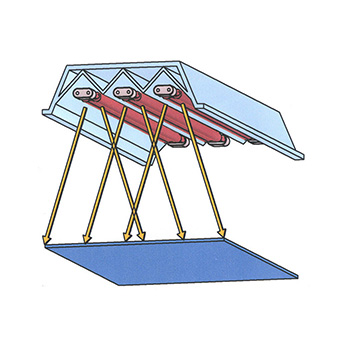
Infrared radiation is applied for…
- Heating
- Welding
- Soldering
- Sintering
- Tempering
- Drying
- Evaporation
- Dehydration
- Adhesives
- Fixation
- Drying
- Activation
- Curing
- Thermoforming
- Blow Molding
- Deep Drawing
- Foaming
- Imprinting
- Shrinking
- Concealing
- Vulcanization
- Lamination
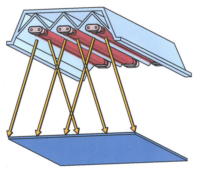
Infrared Radiation...
- has due to the specific features.a varied and individual range of applications.
- depending on the wave length of the light can be divided into long-wave, medium-wave, fast response medium-wave, short-wave and near-UV infrared.
- used in countless applications in Plastics-,Chemical-, Printing-, Wood-, Metal-, Paper-, Textile-, Food- and Automotive Industries.
- can be absorbed directly, reflected or transmitted through the body. All this depending upon the material’s nature. That’s why it is essentially important to find out the optimal emitter type for your specific heating purpose.
- and temperature gradients produce a controllable energy output, adjusted to match the heating requirements.
- the heating modules as well as the controlling and measuring technique are optimally designed. This guarantees optimum efficiency and quality.
- offers a wide range of possibilities to match temperature profiles with customer’s needs. The heat region zoning saves energy and money.
Provides following benefits…
- the process is economical and allows highly efficient heating processes.
- is a clean electrical heat source.
- is fast and immediately ready to use.
- is compact and has a small footprint.
- high heating up rates, due to the large power densities.
- an individually shaped and targeted heat section.
- requires no contact with the material.
- repeatable results can be achieved for consistent process outputs.
The emitter wavelength....
- is customized for industrial applications.The diagram on the left shows the most productive wavelength coverage of 1 – 4 µm.
- and the different designs and burning temperatures of the heating filament on infrared emitters.
- Medium Wave Infrared Emitters: Filament temperature: approx. 850 °C Emissions maximum: 2,0-2,6 µm
- Star Shape Infrared Emitters: Filament temperature: up to 1400°C Emissions maximum: 1,8-2,2 µm
- Fast Medium Wave Infrared Emitters: Filament temperature: up to 1600 °C Emissions maximum: 1,4-1,9 µm (Filament in Star Shape design)
- Short Wave Emitters (double tube/twin tube): Filament temperature: up to 2100 °C Emissions maximum: 0,9-1,6 µm Short Wave Emitters (single tube): Filament temperature: above 2500 °C Emissions maximum: 0,8-1,6 µm
Heating up of plastic by infrared.During the heating up process it should be considered that…
- only the appropriate emitter type achieves efficient and economically advantages.
- Absorption-Diagram on the right shows: Material: Polyethylene 0,1 mm As lined purple Material: PVC 0,02 mm As lined blue Wave length range: 1 – 4 µm Substantial effect of the infrared emitter: 3,2 – 3,8 µm
- physically seen, the emission behavior should,as accurately as, match the absorption behavior. The diagram shows that the directly usable portions of the radiating power obtain a higher efficiency if the emission maximum of an infrared emitter is as congruent as possible with the curves represented in purple or in blue.
- the red curve represents short wave emitters, in light blue is drawn the spectrum Star Shape emitters and the dark blue curve shows medium wave emitter types
Drying water-based paint by infrared…… During the drying process it should be considered that…
- only the appropriate emitter type achieves efficient and economically advantages.
- Absorption Diagram on the left shows: Water, as lined aquamarine.Wave length range: 1 – 4 µm Substantial effect of the infrared emitter: 2,5 – 3,5µm
- physically seen, the emission behavior should,as accurately as, match the absorption behavior. The diagram shows that the directly usable portions of the radiating power obtain a higher efficiency if the emission maximum of an infrared emitter is as congruent as possible with the in aquamarine represented curve.
- the red curve represents short wave emitters, in light blue is drawn the spectrum Star Shape emitters and the dark blue curve shows medium wave emitter types.


